LV Power system design for a wastewater treatment plant with 850 m3/h inlet capacity for an EPC contractor
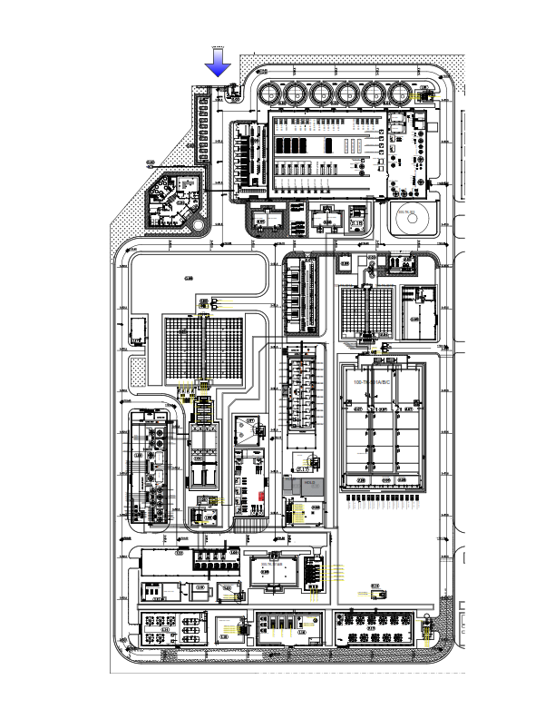
This was a large-scale wastewater treatment plant that consists of 3 main units:
1. Sanitary wastewater treatment unit with an inlet capacity of 550.0 m3/h.
2. Industrial wastewater treatment unit with an inlet capacity of 300.0 m3/h.
3. RO unit
Sanitary wastewater includes three separate streams for three towns. The source of industrial wastewater is steel plant industrial wastewater producers including sand filter backwash drain, regeneration drain of ion exchange columns, boiler blow-down, and cooling tower blow-down. Industrial wastewater contains suspended solids, oil, and dissolved solids.
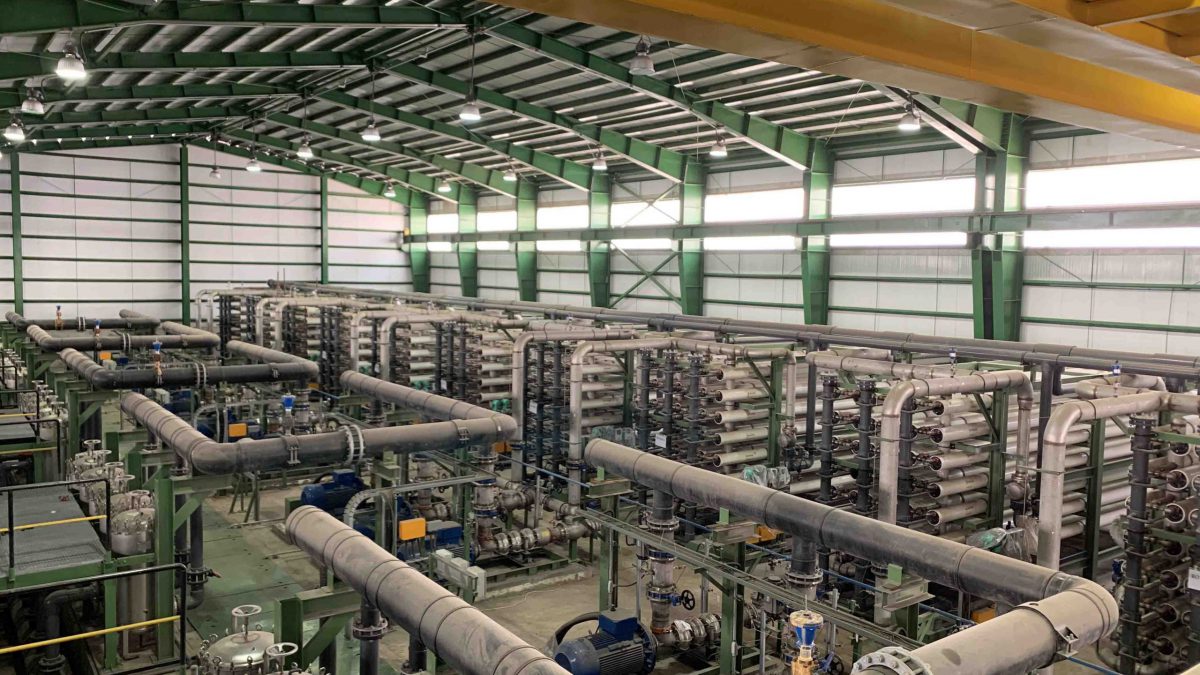
After pretreatment, industrial and sanitary streams will be mixed in a storage tank to feed the RO unit. Half of the RO permeate water will be delivered to the steel factory as industrial water and half of the RO permeate will be transferred to the polishing system to produce soft water.
This project was done in white label format (for 6 months) for the main EPC contractor of the wastewater treatment plants and brought saving money, and time. Besides them, The purchase and construction process was completed earlier.
In the first step, the first revision of the electrical load list of the project was reviewed the number of a power center, MCCs, and their locations were finalized with the civil and piping department of the EPC contractor.
In continuing, the load list was revised according to the technical offer of the manufacturer of electro pumps, blowers, electro fans, etc. then a detailed design of power centers, MCCs, LV cables, and conduit banks, … was designed.
In this project, power electrical software was used like ETAP, EPLAN, AutoCAD
Project specification:
Total consumption power: 10 MW
LV System : 0.4 kv , 65 kA – 1 sec. , 32000A, (2 of 3 logic)
NO. of Power Center: #4
NO. of MCCs: #10(2 of 3 logic)
NO. of Electrical equipment (pump, fan, blower, mixer, etc.): #410
MDL (Main Document List) in the electrical system of this project :
Common Cable Route and Section To Process Units and General Systems
Data Sheet For LV Motors
Data Sheet For Electrical Cable
Data Sheet For Bus Duct
BOM For Cable Tray and Conduit and Other Accessories
BOM For Local Control Station
Data sheet For VFD panels
Data Sheet For Local Control Station (LCS)
BOM For Electrical Cables
Typical Installation Details For Cable Ladder and Trench
Common Cable Route and Sections For Process Area
Electrical Load List For SWWTS and IWWTS substation
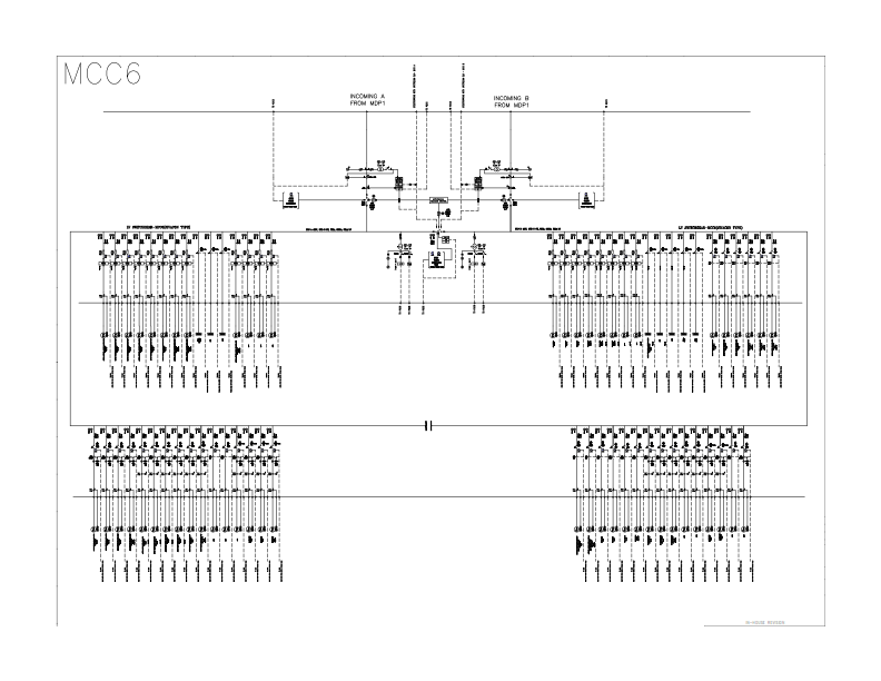
LV Single Line Diagram For SWWTS and IWWTS substation+RO
Power Flow, Short Circuit Study
Equipment Arrangement Layout For SWWTS and IWWTS substation+RO
Cable Route, Cable Tray, Conduit Section, and Arrangement For SWWTS and IWWTS substation+RO
LV Switchgears Data Sheet For SWWTS and IWWTS substation+RO
able Calculation and Cable List List For SWWTS and IWWTS substation+RO
Secondary Earthing Layout
